The major advantage of the humeral interlocking nail is the use of the closed technique during insertion as well as the ability to lock the nail proximally and distally. M/DN Humeral Interlocking Nails range in diameters from
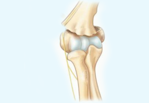
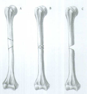
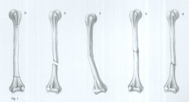
INDICATIONS(FIG.1)
The Humeral Nail is indicated for use in a variety of Humeral Fractures, such as:
A. Segmental fractures
B. Comminuted fractures
C. Fractures with bone loss
D. Proximal and distal fractures
E. Nonunions
F. Delayed unions
G. Pathological fractures
H. Floating elbow
I. Multiple trauma injuries
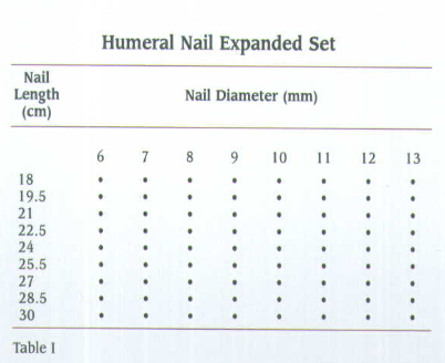
PREOPERATIVE PLANNING
Proper preoperative planning is essential to successful interlocked nailing of the humerus. A template or Ossimeter and an x-ray film of the unaffected extremity are necessary for determining canal size at the isthmus and for measuring the length of the humerus to aid in determining nail length.
Harris/Galante Bulb-tipped Guide Wires (Sounds), available in diameters from
X-rays taken at a 36-inch distance from the x-ray source result in 10-15 percent magnification of bone.
The M/DN Ossimeter has both an actual size scale and one that takes into account this magnification. It should be used routinely to determine nail diameter and length.
The proper length of the nail should extend from
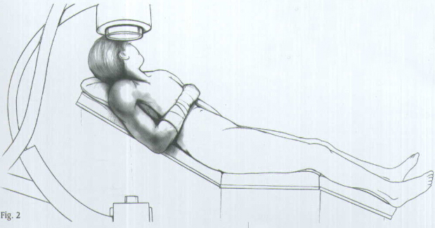
PATIENT POSITIONING AND RADIOGRAPHIC CONTROL
Place the patient in the "beach chair" position with the operative shoulder slightly over the edge of the operative table (Fig. 2). The back should be angled at 45 degrees. Flex the patient at the hip with the foot lowered 20 degrees. Slide the patient to the side of the table so that the shoulder overhangs the table at the level of the scapula. Place a small sandbag beneath the shoulder for elevation.
Place the image intensifier above the arm so that, with the arm abducted, a clear anteroposterior and lateral view of the fracture can be obtained by rotating the image intensifier and the patient's arm. The proximal humerus should also be visible on the image intensifier.
REDUCTION
It is important to reduce the fracture before beginning the surgical procedure.
INCISION AND EXPOSURE
Begin the incision at the anterolateral aspect of the shoulder at the level of the acromion and extend it about
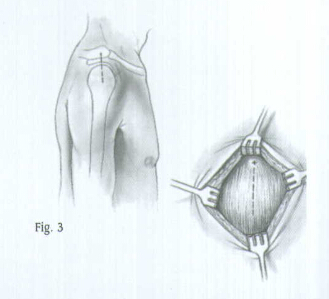
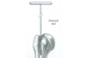
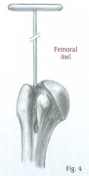
CREATING THE ENTRY PORTAL
Place the Femoral or Tibial Awl at the junction of the articular cartilage and the greater tuberosity (Fig. 4).
Check the position with A/P and lateral views. When the correct position is achieved, rotate the awl to create an entry portal for the Bulb-tipped Guide Wire.
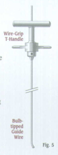
GUIDE WIRE PLACEMENT AND REAMING
Attach the
To aid in manipulation, bend the tip of the guide wire at about a 10°-15° angle
Insert the guide wire through the entry hole and manipulate it down the proximal humerus.
Advance it to the edge of the proximal aspect of the fracture site and use the C-arm to assure proper placement.
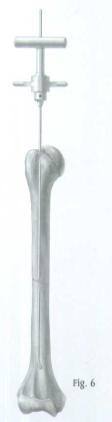
Optional Technique: The
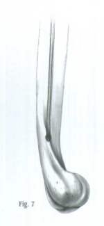
Position the arm to the side of the patient and place traction on the arm to align the humeral shaft. Manipulate the guide wire into the distal fragment under C-arm control (Fig. 6). Then advance the guide wire into the center of the epicondylar region of the humerus (Fig. 7). Remove the Wire-Grip T-Handle.
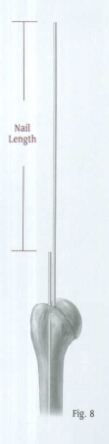
Determine the proper nail length by placing a second guide wire of equal length at the point where the first guide wire enters the proximal humerus. The length of the wire that is not overlapping is the correct nail length required (Fig. 8).
An alternative method is to place a clamp on the calibrated bulb-tipped Guide Wire at the point where the wire enters the proximal tibia and read the length from the calibration marks.
Place the Skin Protector in the wound. Then place an intramedullary reamer over the guide wire and ream the humeral canal. Continue reaming in 1/2 millimeter increments until contact is made with the cortical wall. Ream the humeral canal an additional
Caution: In a comminuted shaft fracture, do not ream across the area of comminution. Ream only in the solid aspect of the shaft. Avoid reaming when there is injury to the radial nerve.
When the reaming is complete and the final measurements are made, insert the plastic Exchange Tube over the Bulb-tipped Guide Wire.
Remove the Bulb-tipped Guide Wire and insert the
Note:
NAIL INSERTION
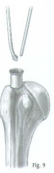
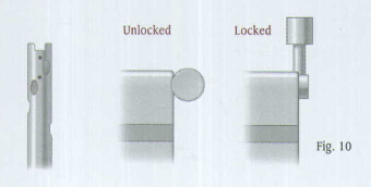
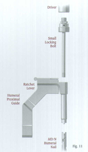
Attach the selected nail to the Humeral Proximal Guide, making sure that the arrows align. A keyway in the proximal end of the nail will help ensure proper alignment (Fig. 10). Lift and turn the ratchet lever 90 degrees to open the ratchet mechanism of the Humeral Proximal Guide. Insert the locking Bolt through the barrel of the guide (Fig. 11). Lift and turn the ratchet lever 90 degrees to close the ratchet mechanism, and use the Pin Wrench to tighten the Locking Bolt into the proximal end of the nail. The ratchet mechanism will prevent the bolt from loosening during insertion of the nail.
Note: If the ratchet mechanism of the Humeral Proximal Guide does not operate freely, it may be necessary to disassemble, clean, and reassemble the mechanism. If the ratchet mechanism becomes inoperative, it may be removed. The assembly will still function; however, the Locking Bolt may loosen during the procedure.
Note: All humeral nails use 4.2 or
Verify proper alignment by inserting the
Screw the Threaded Driver or Slaphammer into position on the Locking Bolt. Insert the nail over the
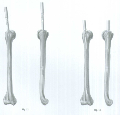
Begin seating the nail using gentle impaction with the mallet (Fig. 12). The nail must advance with each blow of the mallet. If it does not, remove the nail and ream again. While impacting the nail, use the Humeral Proximal Guide to maintain the proper rotation.
Be careful when crossing the fracture site. Visualize the fracture in two planes with image intensification to assure proper passage of he nail into the distal fragment (Fig. 13). Reduce the force of impaction as the proximal end of the nail approaches the humeral head. Nail should be inserted
When the nail is fully seated, REMOVE THE GUIDE WIRE so it does not get trapped in the bone. Remember, it might be concealed inside the driver of Slaphammer.
PROXIMAL LOCKING
The M/DN Humeral Nail has three oblique locking holes proximally.
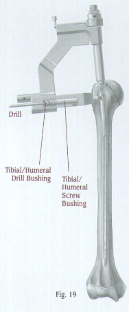
Insert the Tibial/Humeral Screw Bushing through the hole of the Humeral Proximal Guide until contact is made with the skin. Insert the
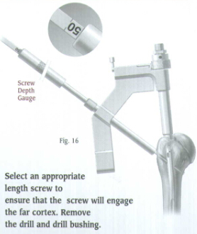
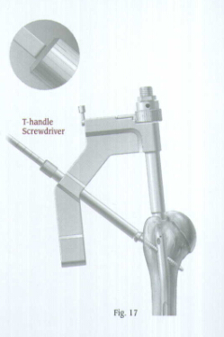
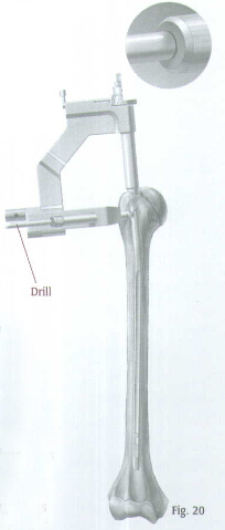
Use the T-Handle Screwdriver to insert the appropriate 4.2 or
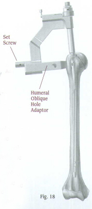
For more proximal fractures, additional oblique screws may be used. Attach the humeral Oblique Hole Adaptor to the Humeral Proximal Guide (Fig. 18). Secure the adaptor with a set screw, and tighten the screw with the Pin Wrench. The adaptor has two holes. One hole is for anterolateral to posteromedical screw insertion. The other hole is for posterolateral to anteromedial screw insertion.
Insert the
Use the T-Handle Screwdriver to insert the appropriate length 4.2 or
If an additional proximal screw will be used, repeat the procedure.
Take A/P and lateral C-arm views to check for correct positioning. Disengage the ratchet mechanism, then loosen and remove the Locking Bolt and Humeral proximal Guide.
Be sure that the humerus has not been distracted during nail insertion and proximal locking. Before locking the nail distally, tap on the elbow or the insertion device to ensure impaction.
The proximal portion of the M/DN Humeral Nail also has three suture holes which allow the use of
DISTAL LOCKING
Technique for Using the Free-Hand Targeting Device
The distal locking screws are inserted with a free-hand technique using the Free-Hand Targeting Device.
The inferior distal hole of the M/DN Humeral Nail is an anteroposterior dynamic slot to help achieve dynamization. The second hole is for static locking. If static locking is preferred, but there is a potential need for later dynamization, insert screws in both anteroposterior locking holes. The locking screw in the static hole can then be removed to achieve later dynamization.
Note:
 个人中心
个人中心 消息中心
消息中心